
| August 17, 2000 | If you build it...they will come... | 6:26 AM |
I pretty much had my heart set on a 4-player station with 10-buttons each, a track ball, spinner, true 4-way joystick with 3 buttons, four player starts and associated coins, ESC, PAUSE, ENTER, and ~ button from the start. Alas, even on a 4 foot wide control panel, this is cramped. You really need to pick what you are going to do a lot of and do that well. So, I made two panels (all hinged at the bottom/back with quick disconnect IDE type cables). One is a 4' wide Guantlet style board for 4-players, with four 8-way joys (players 1/2 have 8 buttons while 3/4 have only 3), and four player start/coin buttons. ESC, PAUSE, and ~ are there, and that is about it. The second (which is actually the first one I finally ended up building, once I realized what I would use more) is a fully featured two player rig. It is closer to 3' wide, and has two 8-way joysticks, 10 buttons each, two player start/coin buttons, ESC, PAUSE, and ~, a 3" track ball as well as two mouse buttons, a true 4-way joystick with 3 buttons (in parallel with the other primary joy/buttons). I may try to add a track wheel (but I'll have to build that myself somehow out of old used mouse parts, since $110 is way too much to spend on something like this).
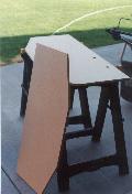
Below, you can see some of the Formica and WilsonArt samples that I was considering. I ended up using the Formica Black Faux Marble (fake marble...grin) on the left, and bought enough for two control surfaces.

| July 19, 2000 | The fun part...colored buttons and drilling holes | 6:26 AM |
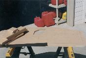
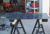
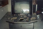
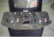
I was able to work on the panel a little today. I decided to complete the smaller 2-player panel first, and my track ball arrived yesterday from Happ Controls, though the mounting plate is still MIA (maybe Monday). As I had mentioned, I was planning on finishing the surface of the control panels in a black marble formica. So, after marking all the locations from a template and some ad-hoc measurments for the control buttons, I drilled a small pilot hole through the center of each location (to enable me to find the centers after the formica was glued on). I also market out the area for the track ball that needed to be cut with a jig saw, and cut that (I would use the router to clean out and trim the area after the formica was added). Then, I began by cutting a slightly oversized square section of the formica out on the table saw, rough marking it for the control panel size, and pre-glued both surfaces with contact cement. Once that was tacky, I flipped the formica over and lined it up and began working it all down. This needs to be done pretty quickly and continuously worked down with a roller, and I should have waited a little longer for the stuff to set before routing/trimming and drilling the holes.
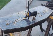
Once the top was down, I got my router out, with the formica edge trimmer out and cleaned up the edges. I had kerfed the edges with my table saw prior to this, and it sort of caused some havoc with the small bearing spinner, but it wasn't too bad (just watch it, the bearing wants to fall into the kerf, and you end up junking the straight edge finish). I also drilled a pilot hole through where the hole for the track ball had been cut to get the router in there and trimmed up the formica on the inside there as well. Now, I let it dry for a little while (not long enough...sigh, as once I began drilling the front holes for the formica, it lifted just a little), and flipped it over. Drilled from the back side through the small pilot holes that I had drilled earlier to just punch through the formica. This leaves a broken and nasty edge, but I'm going to drill out 1-1/8" holes for the buttons and 1-3/4" for the joysticks anyway, so it shouldn't hurt. Now, I just carefully began drilling from the front side with the larger bit, and made sure that the bit had a sharp edge to circumscribe the ring and make a nice edge on the formica. Once all of that was done, I finished out the final punch through in the wood and was done. The only thing left to be done was to invert the joyticks on the face of the panel to get screw hole locations. I carefully drilled down through the formica, and mounted all three joysticks with size 10 1-1/2" carriage head screws, carefully using both flat and lock washers on the back side and not torquing them down too hard.
| August 26, 2000 | Soldering Skills | 11:00 AM |
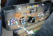
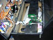
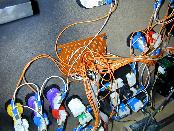
I was now at the point where some soldering and wiring needed to be done. I really wanted to take some care to make this look neat, as I'd seen some of the pics of joystick controls and the rats nest of wiring that was in there. I had lots of little zip ties and some little plastic sticky back anchors to zip tie all the wiring to, in order to keep everything neat and routed. First I started out by wiring about 4 separate ground loop paths. Just so that there wasn't a potential for a fatal catastrophe if one wire broke. Player 1 joystick and buttons were one loop, Center 4-way joy and buttons and MISC 5 were another, Player 2 joy and buttons the third, and the track ball buttons, coin and player starts the final. These all got wired in nice little loops with 20-ga. stranded wire and some small 0.188" couple plugs and the final runs went into a bus bar. For the switched sides, I cut the end of an IDE cable (40-pins) off, and soldered all 40 leads into a small project proto board. The two leads on each end (1,2 and 39,40) were Common or GND lines, and went into the two end bus traces, which I then liberally ran twin leads over to the bus bar. Next, I ran cut-to-length traces from each control and soldered it into each of the IDE cable lines on the project board. Once this was done (and it took a while), I mounted the project board to the bottom of the control panel near the bottom of one of the hinges so that the IDE cable would not stretch when the control panel was opened up. I mounted the KE72 and M24 with screws and some little aluminum stand-off tubes on one of the cross braces above the drawer, but plenty far down below where the control panel stuff (track ball, joysticks, etc.) would reside when in the closed position. These were pointed toward the rear of the cabinet, so it was easy to snake keyboard and mouse extensions out the rear over the top of the drawer unit down to the CPU. All of this finished up pretty well.
| May 29, 2006 | MAME II Control Panel Button/Joystick Layout | 10:03 PM |
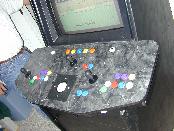
I answer more questions about the control panel and the wiring than any other thing, so I thought I would update this page with a quick layout reference for my Mame II project. I went with a 2 player only control panel, even though it was bigger. I gave more room to each player, had space for a spinner, all the mame control keys, player start and coin slots, as well as dedicated 4-way joysticks for each player. The picture below gives details of what is what.
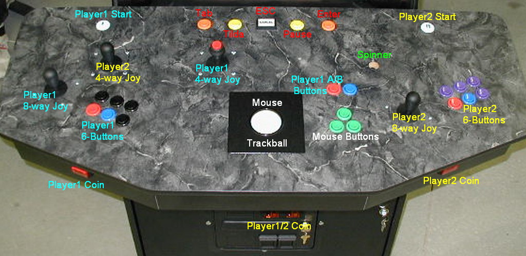
I wired each player's 8-way joystick in parallel with a dedicated 4-way. In the case of Player1, I put it dead center for better feel when playing games like Pacman, Donkey Kong, Galaga, 1942, DigDug, etc. And I put Player2 4-way over on the left. That seems a bit wierd, I know, but in this case, I simply setup all my global games to have P1 Joy2 be the right one and P1 Joy1 be the left one (for games like Karate Champ and SmashTV) and it works fine. Also, the Player1 4-way has a button on top that is wired as a completely separate button, but normally programmed for same response as P1-ButtonA. This is for games like Tron and stuff that you need your right hand free to work the spinner (and some people seem to like playing Galaga with the top button). There are also Player 1 Button A/B alternates just to the right of the center 4-way if you would rather (though left handed players can still use the original Player 1 buttons). These 2 alternate buttons also work great for centipede and/or Tempest type games when you use the trackball or spinner.
The top 5 buttons are the MAME control buttons for setting the volume and stuff (Tilda), entering the config menu (Tab), exiting the game (ESC), Pause, and Enter (this is useful for navigating and entering config menus). Additionally, I have quick press backlit Play/Credit buttons on the front of the control panel for each player. This is wired in parallel with the coin slot, and these can be disabled inside the control panel to require the use of the coin slot if I wish (with the simple use of a 2 pole switch).
Resources are as follows for the Hagstrom 36 control USB combo encoder (a total of 30 total inputs were used):