| August 5, 2000 | Construction ZONE!!! | 7:23 PM |
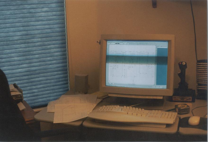
This marked the first day that I actually started work on the cabinet. I had been buying stuff for the construction, and had gotten pretty much everything planned out (including the layout of the most efficient cuts in the two 3/4" 4'x8' MDF and the one 5/8" 4'x8' MDF). I had spent several evenings drafting out the 3D design on Turbo CAD Pro Version 6.2. You can see some of the screen at the right and I have made the full .DWG file (with 3D rendering, 4'x8' cut plans and dimensions) available on the Downloads page. Now all I needed to do was begin. Well, if you have never tried to move 3/4" 4'x8' MDF around by yourself, let me just tell you that it is VERY DIFFICULT. My wife helped me put the first one on the saw horses the night before, but today, I was on my own.

The biggest problem with 4'x8' sheets, is that you can't easily get them on a table saw. Most of the smaller pieces, I made gross cuts with a skill saw, and then shaped them down to the final dimensions with nice straight lines on the table saw using the fence and T-square. But there was NO WAY I was going to be able to get the side panels up on the table saw for final trim. So, I tried running jigs clamped to the 4'x8' to help align the skill saw. That also didn't work well. For some reason the skill saw wouldn't feed like a table saw and the blade would bind up when I had a jig/fence on the work surface. So, I went back to free-hand with the skill saw. It went ok, but my skill saw sucks (and my free hand ain't so good either...especially after a couple 32-oz. cups of coffee).

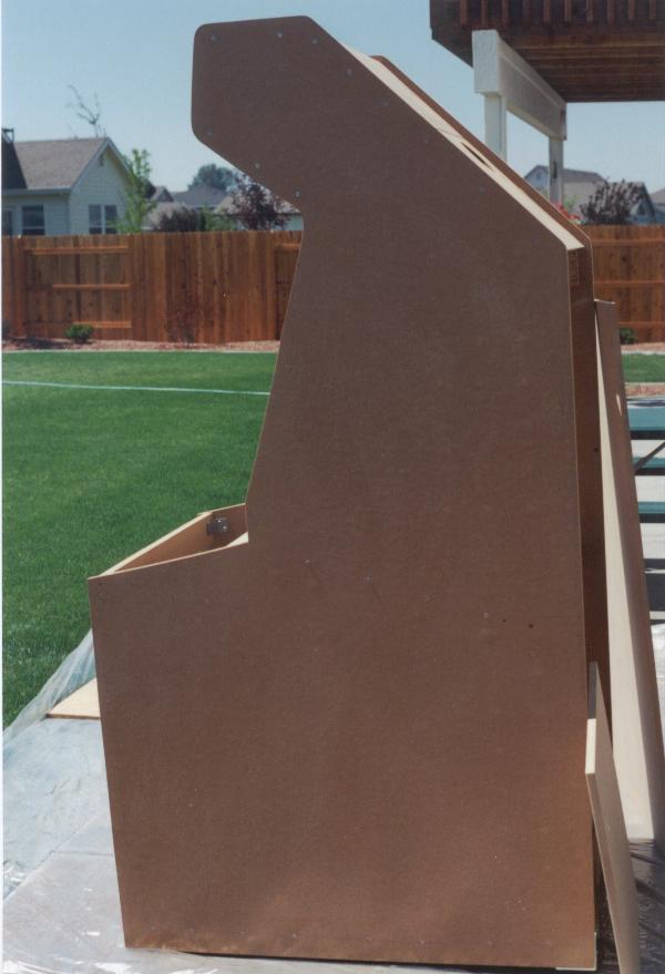
I eventually got both the side panels cut out (combination of skill saw and jig-saw worked ok). I ran one of my spline curves around the sharp corners and rounded them on roughly a 2" radius with a jig-saw. Noted that some of the edges and cuts weren't EXACTLY matched up, when I stacked them side-by-side, so I laid them back down on the saw horses, stacked, and trimmed them back even (trying to get as close to the original dimensions as possible). This is where I was glad that I'd cut them with just a LITTLE slop from the original dimensions, so I had some material to work with to even them up without shorting myself on final material.
Once this was done, I began putting the bottom together. I used a two-piece for this, since it worked out better in the 8'x4' sheets to have it in two parts. I started by screwing the 3" kick plates to the bottoms (this will provied for a 2-3" elevated, floor). Looking back (once I put the roller wheels on), I wish I had made this closer to 5-6" of kick plate, and recessed the floor to around 4" high, but it worked out in the long run. I also would DEFINATELY cut any slots for the recessed wheels that you are going to do NOW. Same goes for the leg levelers and level plates.
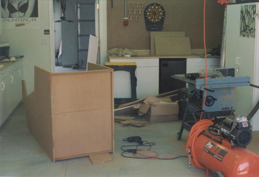
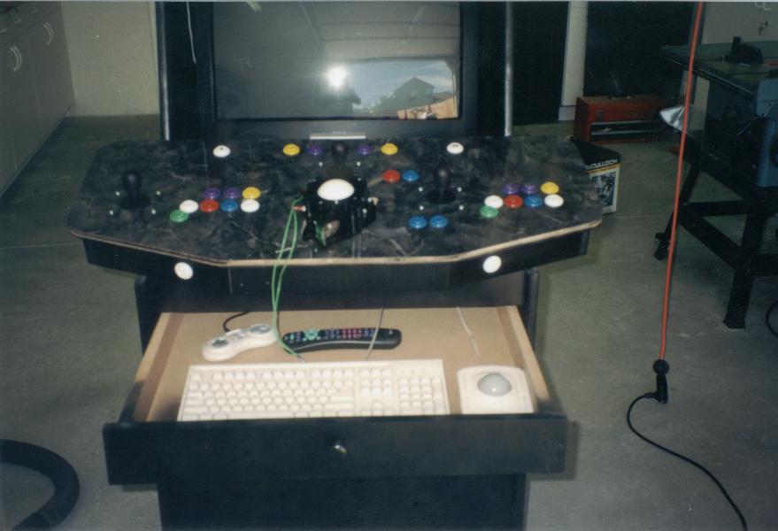
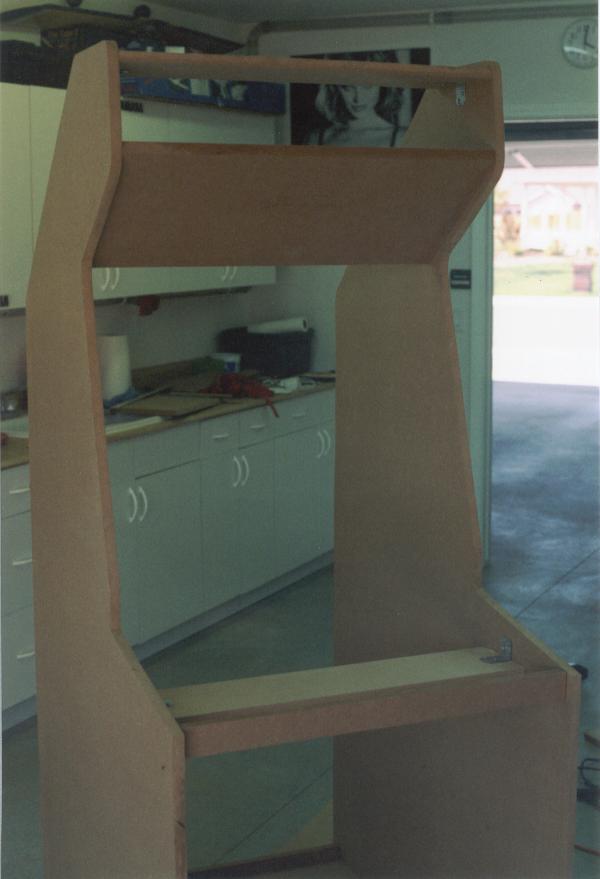
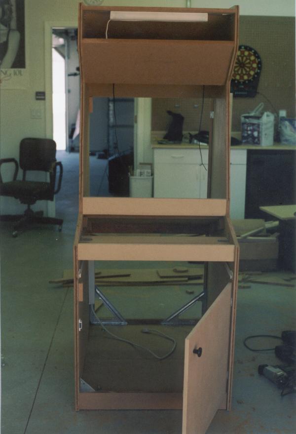
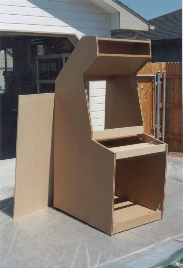
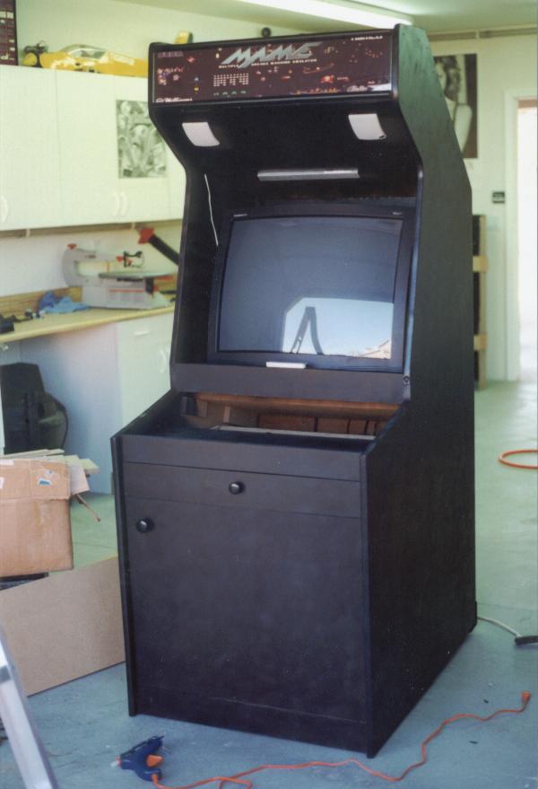
Next, I screwed the floor to both of the side panels, with the side panels lying on their back edges. Then I proceeded to the top under side slant, main top, and back slant for support. I went ahead and screwed L-brackets into this for better support in addition to the counter-sunk screws from the sides. Note that all of the cross pieces are recessed roughly 1" from the extreme edge. This helps make it look a little more 3D, and gives you room to route T-molding slots in the edges for finish work later. Next I added the front spacer panel above the drawer and another internal cross support behind that at a perpendicular to the front face. Finally, I lined up the TV platform, and actually screwed in runner supports for this and then put the TV platform on top (for better support). I also added a 2x4 cross support directly behind the TV platform.
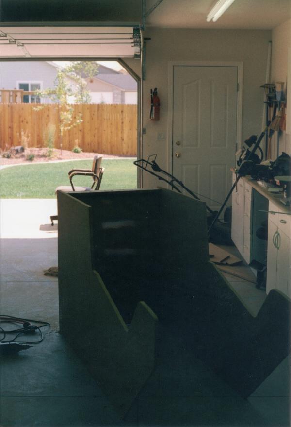
And this is what I ended up with after the first day...
| August 12, 2000 | More work | 8:00 AM |
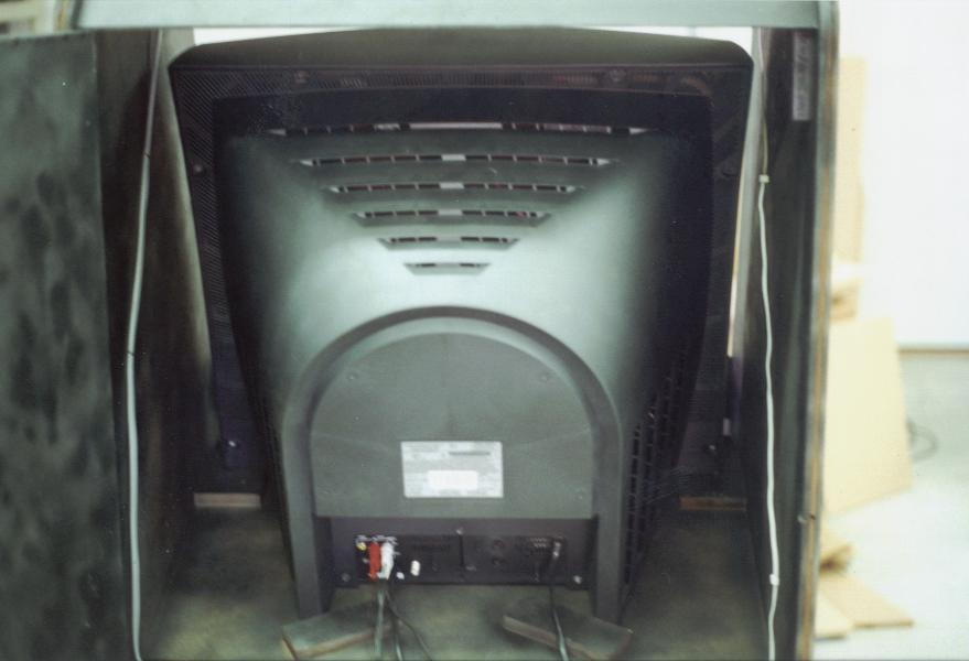
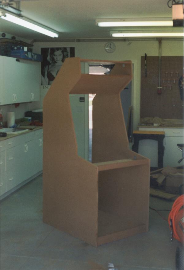
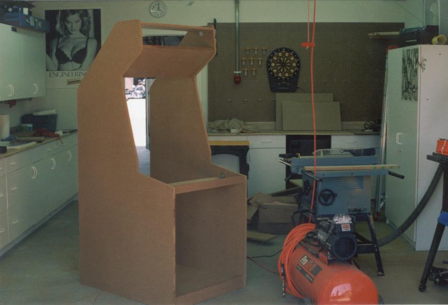
I started by putting some small blocks of wood in key places on the TV platform to help support the TV and keep it from sliding back down the platform. I also added metal corner brackets to all four bottom corners for vertical side-side stability, since having all of those access doors (front and back) really can weaken the cabinet. Cut the holes for the two small fans in the rear slant top, and cut the rear and front doors out of 5/8" MDF. Began the "add-hoc" design and creation of the 3.5" high slide drawer that would go into the front, and mounted everything on the cabinet.


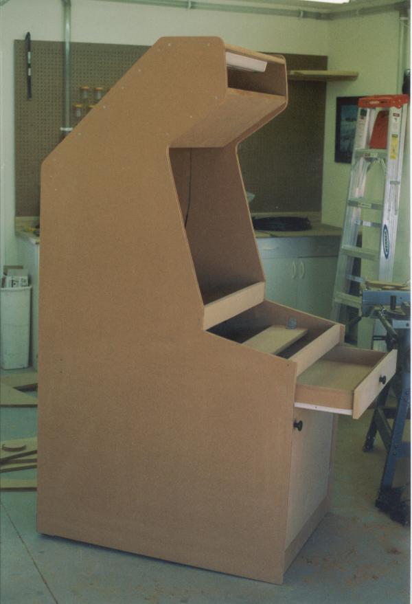
Finally, I began to work on a way to kerf the edges of the side panels for the T-molding that would be put on as final trim. This sucked. the panels are too big to run across a table saw (even if they weren't bolted together), and a hand skill saw would only end up killing someone. I have a router, and probably should have attempted something with this and some jig to line it up, but I went ahead a bought a new dremel tool, complete with a small router base and a 1/8" cut bit. I worked out a jig to make it line up ok, and began working on it. Screw me...this took forever, and was dusty and actually ended up looking like crap (even with the jig, this didn't go straight or neat). I'm also worried that the 1/8" cut is going to be too big for the T-molding slot, but we will see. Even if I had managed to get the side panels run across the table saw, I wouldn't have been able to get into some of the tight inside corners of the top below the marquee. This was even tough for the dremel tool. Again, this just plain SUCKED. If I could have found a router bit that would have allowed me to hold the router at a 90' angle to the side panel edges (sort of a 3/32" rotating cut wheel or disk), then it would have been infinitly easier, but I couldn't find one ANYWHERE. This was acutally a huge bulk of the day.
| August 14, 2000 | Sore and tired | 8:00 AM |
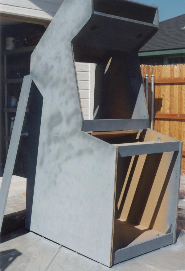
I started out here by vaccuuming up all the filthy saw dust that had been collecting over the past couple work days. Then, I began the detailed process of cutting and lining up the front plexiglass. I used some 1" aluminum angle material and used the PVC marquee mounting plastic for the sides that I got from Happ Controls and placed a small line of double-sided insulation weather stripping tape to prevent vibration. The bezel should cover most of the rest of the back ground up. Went back and attatched the leg leveler pads and plates, and did some retro modification to the bottom to accomodate the recessed wheels (this should have been done first to the bottom as I mentioned earlier). Also began working out how to put the satelite speakers from the cheap powered computer speaker package that I got. Ended up taking the speaker fronts off the plastic square boxes and drilling two 2.5" holes in the front slant panel below the marquee and mounting the roughly 3.5" x 5" square speakers in there. Unfortunately, while drilling out the mounting holes, I punched through the front of one of the plastic face plates, and the drill bit ate the cloth mesh covering on one corner. Also mounted the volume control on an L-bracket inside the front door cabinet.
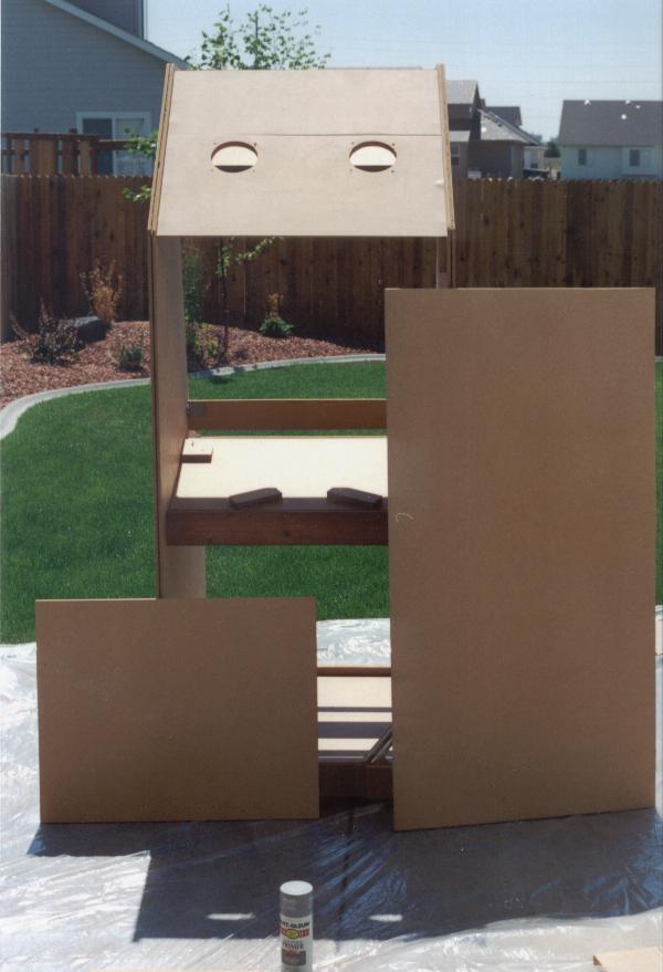
Finally, I began taking everything apart and unscrewing all the hinges, drawer slides, knobs, latches, etc. in preparation to paint the whole thing. I'm not done with the control panel yet (and I'm still sort of beating around some different ideas on exactly how I want to attach the thing to the main cabinet), but I need to get this painting and stuff done before I can continue with the final mounting and stuff. I found some Krylon primer and some black "chalk-board" paint that should give it a rough cabinet look and hide scratches and stuff. Looking back, I'm not so sure I like this paint as much as I thought I would, and a semi-gloss black might have been better. The painting was arduous and HOT.

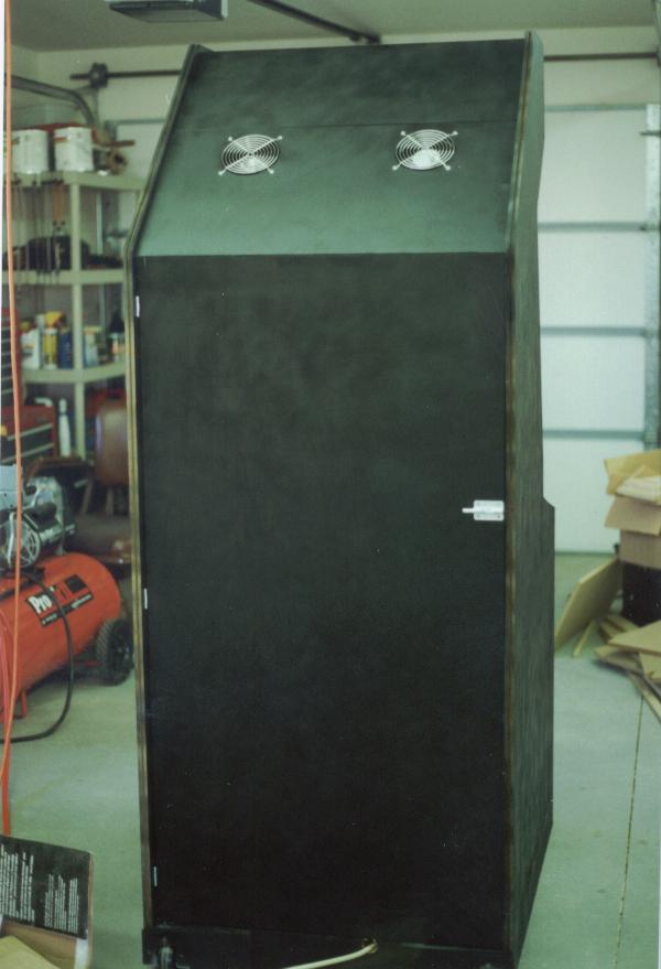

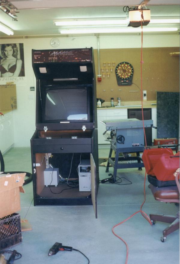
As a last little deal, I got everything put back together (back/front panels, hinges, drawer slide, knobs, etc.) after painting and put the whole computer, TV, etc. together. I even wired the fans and the marquee light up and got it all hooked into a little power strip that is attatched inside. Flipped the switch, powered up the computer and held my breath...it worked, and it looked pretty cool (still no bezel or control panel, and I haven't got the marquee between the plexiglass yet as I was worried the print job might get ruined while I'm working on all this stuff). I played some Galaga and got the volume balance between the TV speakers and the computer powered sub/satelite speakers set. Man, that thing ROCKS! I spent almost $20 in quarters just hitting the '5' key to hear that coin sound...can't wait to get done with the Control panel and move this beast into the house.
| August 16, 2000 | Finish Work | 7:00 PM |
I'm now at a point in the construction where a lot of little 1-2 hour projects can be completed without a huge ordeal or having to get all dirty. This is nice, since I only have about 2 hours after work to do anything. Anyway, I got the Marquee printed out at Kinkos for $16 from the original .tif file that is available on my Downloads page courtesy of Richard. They printed it in color on an HP 2550, and it looked pretty good. Anyway, I took tonight to cut the plexi-glass into two 7"x28" sections, and sandwiched the print between these two, and secured them to the top marquee location (with the flourescent light behind it) with some of the marquee PVC stripping from Happ Controls (incidentally, this is also what I'm using to secure the plexi-glass TV cover). I stepped back, flicked on the marquee light, dimmed the lights in the garage, and a big grin spread over my face. NOW it is REALLY starting to look like a TRUE arcade machine. I'm tickled to death with how good it looks. The back lighting shines through the ligher printed areas, the blue from the "MAME" logo virtually glows, and the white of the starts sparkle. I'm very happy.
I also found time to glue the T-molding into the edges. Now was the moment of truth to see if all that work was going to be for nothing. To tell you the truth, this was one of the cooler trim ideas I'd had, and it hadn't been going as well as I'd hoped. Up until now, the plan had been more trouble, and turned out not looking as clean as I'd hoped (and it had taken 4 times as long as I'd expected), so I was a bit tenative. Anyway, I'd tried gluing some sample sections in some test pieces of wood using wood glue, silicon, and a couple other things. They had all turned out less than stellar. Then Jason mentioned that he had just used hot glue gun to run a bead in there and push the T-molding in. My experiences with hot glue guns have not been good (yes, I burn my fingers, get glue all over, and generally, the glue cools before I can get it where I want it). Anyway, I figured I'd give it a try. Turned out to work very well, actually. I went through 27 sticks of glue, but it finished up very nice, sticks well, was easy to align it as I went, and should be just fine. Now that I'm planning on kerfing the slots on the control panels with my table saw, this should finish up a breeze!
| August 19, 2000 | Attaching the Panel | 4:00 PM |
Ifter playing a golf scramble this morning, I came home and worked on the Control Panel for a little while. Once that was done, I still had to work out how I was going to attatch the thing to the cabinet (oh, I had an idea of how it was going to work out, but the specific implementation was going to have to be done on the fly). I wanted the cabinet to latch down at the front, near the monitor, and be hinged on the back, where all the wires would be run. As it turns out, I just extended the front edge of the skirt a little bit on the control panel and it held itself up at the right angle, and I could latch it all down just fine. And with a couple offset blocks on the back skirt, the hinges went on just fine as well. Not sure how the larger 4-player panel is going to work out, but I'll worry about that later.


| August 26, 2000 | Finish Work | 10:00 AM |
I just had a little bit of stuff to finish up on the cabinet. I got most of the panel hooked up and hinged the way I wanted. I had to drill a couple holes (I wanted to put a co-axial cable connector on the rear to feed CATV into the cabinet for the TV (heheh, don't want that 27" to go to waste). Unfortunately, the bezel that I put on with the lexan, also covers up the IR for the remote to the TV. I tried drilling some holes, but the best way to get the TV to respond is still holding the remore as close to the TV and angling it down while frantically pressing buttons.
As I mentioned, I placed the lexan and bezel on the cabinet. Basically, I just put some light aluminum angle frame behind and sandwiched the bezel and the lexan between that angle frame and some of the marquee black plastic and then screwed it all into the sides from the rear. If I were to do it again, I would make a couple of wood blanks all around the edge, and then bolt the lexan and bezel to it from the rear to make it look more finished.